Butterfly valve
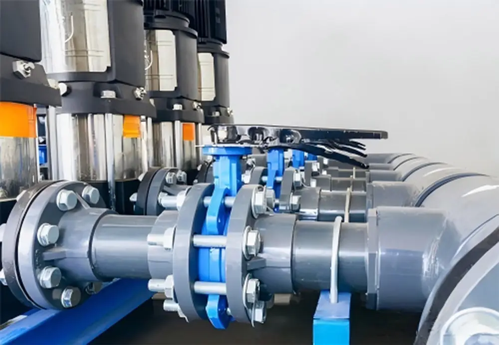
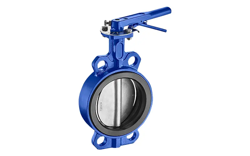
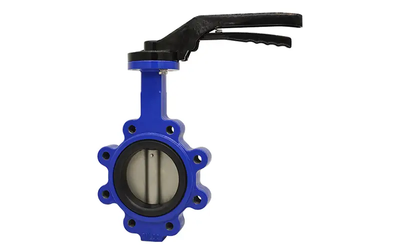
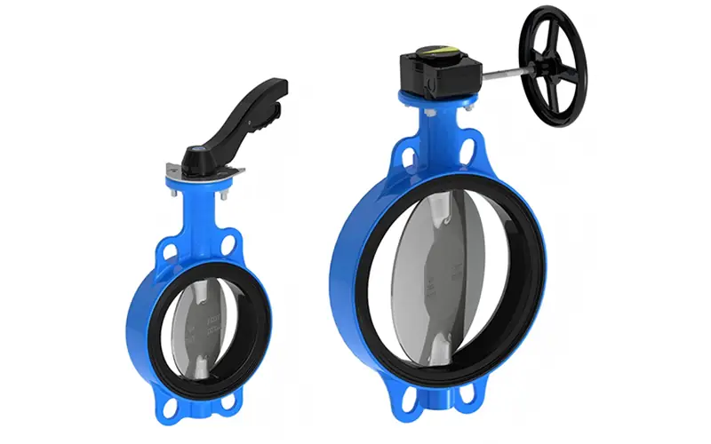
Butterfly Valve Series delivers precise flow control and reliable sealing for diverse fluid systems. Available in wafer, flanged, and fire-fighting signal types, these valves excel in compactness, ease of operation, and durability, making them ideal for water, sewage, gas, and industrial fluid applications across municipal, industrial, and fire-fighting scenarios.
Butterfly walve

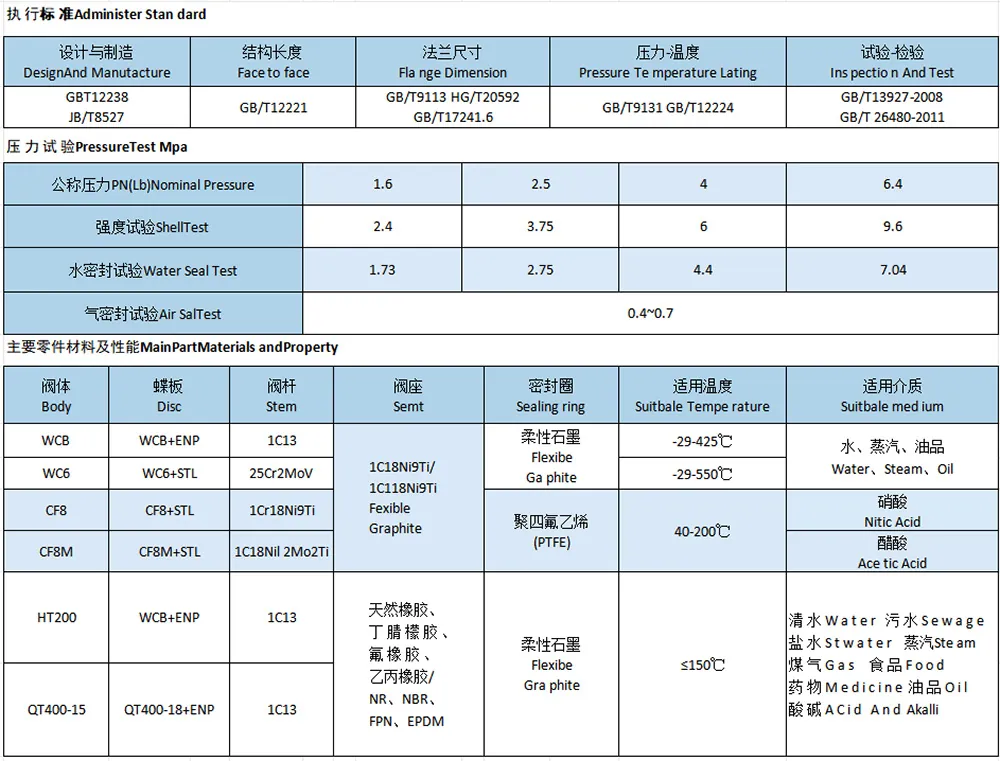
Butterfly valve series adheres to stringent execution standards covering design, manufacturing, structural length, flange dimensions, pressure-temperature ratings, and inspection/testing, as specified by GB/T12238, JB/T7527, GB/T12221, GB/T9113, HG/T20592, GB/T12241.6, GB/T9131, GB/T12224, GB/T13927-2008, and GB/T26480-2011.
Selection Guide
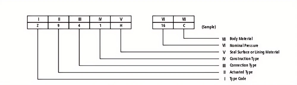
| Code | 0 | 1 | 2 | 4 | 5 | 6 | 7 | 8 | 9 | |||
| Ⅱ-Actu ated Type | Ekcto magneti | Becto-hydauli | n | Gear | Spurgear | Angle gear | Pneu matic | Hydraulic | odani | Electrical | ||
| Ⅲ-Con nection | Inside g rew | Outile srew | Fange | Web ing | Wafer | Union ring | Compression joint | |||||
| I-TypeCode | V-Construction ype | |||||||||||
| Gate Vale | Z | Rbing stem | on-rising stem | |||||||||
| Wedge type二 | Paralle type | Wedge type | Paralleltype | |||||||||
| Flexible | Rigid disc | |||||||||||
| Singe | Double | Single | Double | Single | Do uble | Singe | Double | |||||
| Glo be Vakve | J | Th rough way | 7.Type | Tee | Angled | Straght fbw | Balance type | |||||
| Tho te Vahe | L | Thyough way | stand | |||||||||
| PstonVahes | U | |||||||||||
| BallVakve | Q | Half ball through way | Foatingtype | Tun nian-mounted | ||||||||
| Throughway | Y-Pattern Tee | Seal type | Tee | Fo uway | Thro ugh way | Tee | Top type | Allwek ing | ||||
| L-Pattern | T-Pattern | T-Pattern L-Pattern | ||||||||||
| Butterfly Valve | D | Hon-seal ti eccentic | seal type | lon-saltype | ||||||||
| Center linetype | Singlecentrie | Breccentric | Linkmechanism | Trieccentric | Center linetype | Bi-ecce ntri | Linkmechanism | Ti-ecentrie | ||||
| Diaph agm Vahe | G | Weirtype | Go be type | Y-pattern | Through waytyp | Rpatemangk type | ||||||
| Plug Vahe | X | Packing seal | Lubricateseal | |||||||||
| Thughwaye | TratemEe | Fourewaype | Though waytype | Tee Ttype | ||||||||
| C | H | Liftype | Swing type | Rotary type butterfly | Gilobe check | |||||||
| Th.way | Verticltype | Angle type二 | Single plate | Do ubled sc | Multi-disc | |||||||
| vaNe | A | Sping saltype | Sping ureal | Lever | Sping uneal | Pu be | ||||||
| Ttwith cooling fin | Low ift | Fullit | Spannertype | Fulit with control | Spannertype | |||||||
| Tw in-bw | Tw in-bw | Low ift | Low ift | |||||||||
| Red uc ing Valve | Y | Diaphragm | Spring diaph agm | Pston | Be lows | Lever | ||||||
| Tapváave | s | Ballfbat | Open bucket | Exp nsion | Inverted bucket type | Membrane box | Puke | Hotmotive force | ||||
| Waste Valve | P | Contin uous Discharge二 | Dscontinuous de charge | |||||||||
| Though waytye | Angletype | Stajmfwtye | Stajmfwtye | Stajmfwtye | Stajmfwtye | |||||||
| 1omna The dat of mom na da meter expDes5ast ntimes MHa va e;twil akworking presure when medium te me atre over42 CAnd be used in powerstaton. | ||||||||||||
| Code | Code | VI-Body mate ial | Code | VI-Body material | Code | |||||||
| Ba bitt me tal | M | lybn plastik | H | Ta nium&tit nium alby | TI | Sphero ida lcast iron | Q | |||||
| Ena mel | C | Boroneingstel | P | Carbonsteel | C | Mo2Tiseries 5 | R | |||||
| itrided steel | Lead Lining | Q | Crl3 s ries 5S | H | Pastic | S | ||||||
| Fluo ro plastics | F | Mo2 Tise res 55 | R | CFMo steel | I | Coppe &Coppe rAlly | T | |||||
| Ce ame metl二 | G | Pbstic | 5 | Ma lea blelron | K | C-Mb-Vstel | V | |||||
| Cr13 sres55 | H | Coperalloy | T | Aluminum alloy | Graycast Iron | Z | ||||||
| Rubbe lined | Rubber | X | 18-8 series 55 | P | 18-8 se res 5S | |||||||
| Monel metal | J | 18-8 series 5S | PL | |||||||||
| Re mark:1 、Code Wis express material of seatsurface that direct | Re mark:1 、Omitthe ode if body mate rialis gray castiro n body when | |||||||||||
| machining from body. | PN≤1.6MPa and is carbonsteel body when PN≥2.5MPa. | |||||||||||
| 2 、Exce pt diaphragm valve,it markwith lowhard ness | 2、CF3、CF8、CF3M、CF8Metc ma te rialcode can direct ma rk | |||||||||||
| mate rialcode whensealsurface ma te rialis diffe rent. | on body. | |||||||||||
Product Features
Application
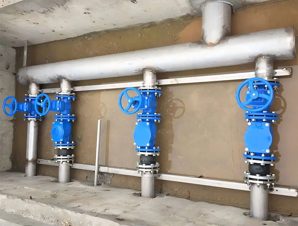
1. Pipeline systems for drainage, sewage treatment, irrigation, and municipal engineering.
2. Medium flow control and regulation in industrial pipelines such as power plants, metallurgy, and petrochemical plants.
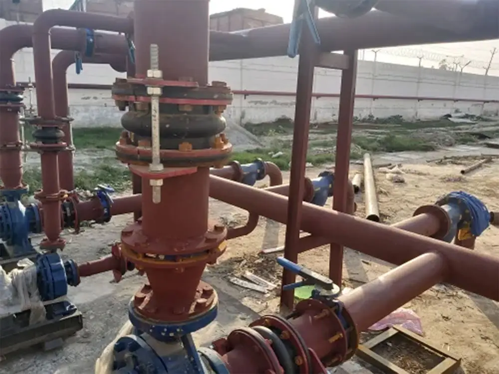
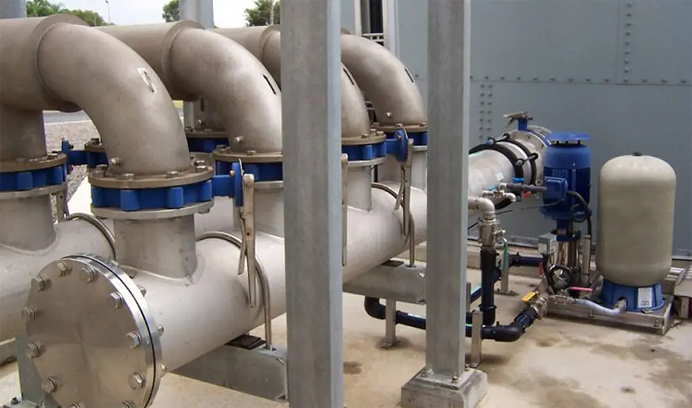
3. Water, sewage, air, oil, and mildly corrosive media.
4. Rapid opening and closing and flow control of large-diameter, low-pressure pipelines.