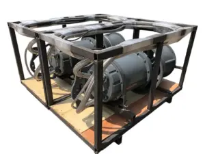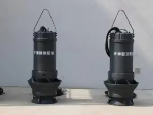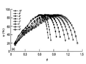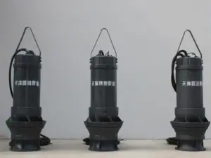
Pump intake design aims to deliver suitable flow to the pump inlet across the site’s operating conditions. Start with the approach path, liquid, water levels, and running-pump combinations, then confirm the applicable geometry, inlet requirements, and evidence needed to review the layout.
A pump curve describes the proposed equipment, but it does not establish that the surrounding structure will supply good inlet conditions. A layout may need review beyond the immediate pump opening. The upstream approach and the way the station operates belong in the same information pack.
This guide explains how to organize that review for water-transfer and drainage projects, including submersible mixed-flow applications. It provides questions, document checks, and a review table. Final dimensions and acceptance criteria must come from the applicable design basis and equipment documents.
Key Takeaways
- Identify the intake type and liquid before applying geometric guidance.
- Review approach flow, water levels, and operating combinations together.
- Keep submergence, NPSH, cooling, and maximum immersion limits distinct.
- Use the applicable standard and model evidence for the actual layout.
- Retain assumptions, drawing revisions, and open questions with the design record.
Define the Pump Intake Design Basis
Identify the intake type and liquid
Begin pump intake design by stating what the structure receives and how it connects to the pump. A free-surface sump is not the same design problem as suction piping connected to a pump nozzle. Define that boundary first. It tells the reviewer which guidance applies.
Also describe the liquid. Clear-water transfer and a solids-bearing wet well need the appropriate design context. Avoid taking a drawing intended for one application and assuming its proportions suit another.
The ANSI listing for ANSI/HI 9.8-2024 describes the standard’s scope for new and modified rotodynamic-pump intakes. Its public description identifies uniform, steady inlet flow, with control of swirl and entrained air, as design objectives. The listing is an overview, not the full standard’s dimensional or acceptance requirements.
Record duties, levels, and pump combinations
For pump intake design, record individual pump duties as well as the station arrangement. Include the relevant water-level range, proposed controls, and which units may run together. Give the reviewer the basis for each condition rather than only a total station flow.
Use the design-flow and TDH input guide to prepare the hydraulic requirements. Total dynamic head, or TDH, belongs to the system duty calculation. This article uses those inputs without repeating the sizing method.
Illustrative scenario: Two drawings use different reference water levels for the same proposed intake. Before comparing pump intake design options, the project team asks for one agreed level basis and a clear revision record. This is a hypothetical coordination check, not a customer project result.
Send Kairun your intake layout and duty information to request the relevant model documents and identify equipment questions that remain open.
Trace the Approach Flow Before the Pump Inlet
Look beyond the pump bay
Trace the route from the incoming water to the pump inlet. Mark channels, openings, screens, gates, transitions, and nearby structures on the current drawing. Identify changes that the responsible designer needs to assess.
Pump intake design should retain that upstream context. A drawing cropped around the pump may leave out a feature that matters to the approach flow. Include enough of the layout for the reviewer to understand where the liquid comes from.
Record the operating condition associated with each drawing or observation. A water-level photograph without its flow or running-unit context may be useful background, but it does not settle every design case. Ask what additional information is needed before treating it as evidence.
Distinguish the concerns being reviewed
Uniformity concerns how flow is distributed at the inlet. Swirl concerns its rotational component. Entrained air concerns air carried with the liquid. These questions overlap in an intake review, but they should not be collapsed into one unexplained statement that the flow is acceptable.
Use a pump intake design record to connect each concern with the evidence required. Do not treat noise or vibration alone as a confirmed diagnosis of a particular vortex or inlet defect.
| Review question | Information to retain | Decision still needed |
|---|---|---|
| How does water approach the pump? | Current layout and operating cases | Which conditions need assessment? |
| What structures affect the approach? | Screens, gates, openings, and transitions | Are their effects addressed? |
| Which inlet conditions are required? | Applicable model and design documents | What evidence demonstrates suitability? |
| What has changed? | Drawing and operation revisions | Does the earlier review still apply? |
Keep general piping recommendations within their stated scope. A straight-pipe rule taken from another application is not automatically a spacing rule for a free-surface pump sump. Pump intake design needs the geometry and boundary conditions of the actual proposal.
Review Submergence Without Confusing Other Limits
Define the reference points
Submergence describes a depth measured between a liquid surface and a defined inlet reference. Before using a value, establish where it is measured. Keep that reference on the drawing so the designer, supplier, and site team read the same dimension.
The Hydraulic Institute’s submergence tutorial defines its variables and describes a relationship for the inlet configurations discussed there. Its diameter is an inlet dimension with a stated definition, not an arbitrary pump outlet or motor diameter.
In pump intake design, a formula is useful only when its definitions, units, and application conditions match. If that match has not been established, request clarification before calculating a site dimension. A familiar-looking equation does not approve an unfamiliar geometry.
Keep the separate requirements visible
Net positive suction head, or NPSH, concerns inlet head relative to the liquid’s vapour pressure. The HI tutorial notes that satisfying the NPSH requirement may call for greater submergence than the surface-vortex relationship alone indicates.
Motor cooling and maximum permitted immersion introduce other equipment limits. Ask for the relevant manufacturer information rather than assuming that one water-depth figure covers all of them. Pump intake design should carry those separate checks into the layout review.
| Term or limit | What to clarify |
|---|---|
| Water level | Which operating condition and elevation datum apply? |
| Submergence | What inlet reference and geometry define the depth? |
| NPSH | What site condition, model requirement, and margin apply? |
| Cooling requirement | Which instructions apply to the proposed motor arrangement? |
| Maximum immersion | What equipment limit applies, and how is it measured? |
Do not replace these checks with a universal minimum depth. Keep the assumptions and the supporting documents beside the result. If the proposed model changes, ask whether its inlet and cooling information also changes.
For pump intake design, the useful deliverable is a traceable requirement for the actual case. List the water levels checked. Mark what still needs confirmation. A single depth copied from a catalogue is not that record.
Compare Sump Geometry and Running-Pump Cases
Match the structure to the design context
The HI public contents for the 2024 intake standard distinguishes structures for clear and solids-bearing liquids. It also lists inlet-bell diameter, submergence, physical model studies, and computational fluid dynamics as separate topics. The contents identify subjects to review; they do not provide their full criteria.
For pump intake design, identify the proposed sump or intake arrangement before selecting a geometric rule. Retain the relevant model dimensions, site constraints, and liquid information. Do not choose a structure solely because a similar station uses it.
Review the connection between pump and structure with the supplier’s actual documents. If a layout assumes an inlet shape or position that the model drawing does not confirm, mark it open. Resolve that interface before treating the geometry as established.
Review the operating combinations that matter
A station may operate with one pump, several pumps, or a different set during maintenance. List the combinations that form part of the project basis. Associate water levels and individual duties with those cases.
Illustrative scenario: A team has reviewed a pump intake design drawing for the planned all-units-running condition. The operating schedule also includes one-unit operation, but that case is absent from the review pack. The team adds it to the questions for assessment without inventing a flow-field result.
Use the pump-curve and operating-point guide to understand the equipment-side information. The intake review must still address the conditions surrounding the inlet. Neither document replaces the other.
If the operating schedule changes, ask whether the previous pump intake design evidence covers the new cases. Keep that decision with the revised schedule. Do not assume that an assessment of one condition automatically proves every other arrangement suitable.
Know What Pump Intake Design Evidence Is Still Needed
Check the applicable basis and source limits
Identify the standard edition and manufacturer documents specified for the project. Use the complete applicable requirements when carrying out a compliance review. Public summaries, a contents page, or this article cannot substitute for that work.
The ANSI listing explains that designs outside the standard’s stated criteria require a physical model study for compliance. Determining whether a particular layout reaches that boundary needs the applicable requirements and a qualified review. This guide does not declare a proposed sump compliant.
In a pump intake design enquiry, ask which assumptions the supplier or designer has accepted. Separate a proposed arrangement from one supported by the agreed evidence. Retain the source and revision behind each conclusion.
Define the study question before choosing a method
If further study is needed, state what must be assessed. List the geometry, liquid conditions, duties, levels, and operating combinations that the study should represent. Ask what outputs, limitations, and acceptance basis will be reported.
Computational fluid dynamics, or CFD, and physical hydraulic models are study methods with defined purposes. The HI contents lists both topics, but that alone does not establish that one can replace the other for a particular compliance decision.
For pump intake design, request an explanation of how the chosen method addresses the actual questions. A coloured flow image without the represented conditions and assessment basis is incomplete evidence. Keep the study scope and report with the layout it evaluates.
For example, an open pump intake design item might ask whether a revised gate opening is included in the assessed geometry. Record the drawing revision, the reviewer, and the response required. If the study uses an earlier opening, ask what follow-up is needed before closing the item. This is a document-review example, not a prediction of the gate’s hydraulic effect.
Prepare a Reviewable Intake Information Pack
Keep inputs, evidence, and open items together
Use one current information pack for pump intake design. Include the layout and sections, elevation datum, water levels, liquid information, equipment references, and operating cases. Label assumed values and identify who will confirm them.
| Record | What it should show |
|---|---|
| Design inputs | Required duties, levels, liquid, and operating combinations |
| Layout | Geometry, inlet references, upstream features, and revision |
| Equipment information | Model-specific inlet, operating, and cooling documents |
| Review or study | Scope, represented cases, results, limitations, and references |
| Open-item register | Question, responsible party, next action, and status |
Use Kairun’s QH model information to begin a model enquiry. Request the current inlet and installation documents for the proposed equipment. The product family page is not an approved site layout or model-study report.
Resolve changes before closing interfaces
Illustrative scenario: Near the end of a review, an intake opening changes on the civil drawing. The study report still references the earlier layout. The team asks whether the change affects the report’s conclusions and records the response before closing that item. No performance improvement or project approval is implied.
Connect the pump intake design record with the installation layout and retrieval checks. The hydraulic review and the practical installation interfaces must describe the same proposed equipment and structure.
Keep the response to each change beside the revised drawing. A new drawing number alone does not explain whether earlier evidence remains applicable. Make that decision visible to the people who receive the final information pack.
Questions Before Accepting an Intake Layout
Is more water depth enough?
Not by itself. Pump intake design also considers approach conditions, geometry, operating cases, and equipment requirements. Check why the depth is required and what other conditions remain unresolved.
Can one spacing ratio fit every sump?
No. A ratio has a defined geometry and application basis. Identify those conditions before using it. Do not apply a piping recommendation as a universal rule for a free-surface intake.
Does CFD prove compliance?
Not automatically. Confirm the applicable standard, required study method, represented conditions, and acceptance basis. A simulation result must be assessed within that scope, rather than treated as general approval.
Which information should I send for review?
Send the layout and sections, duty schedule, water levels, liquid data, proposed model, and running-unit cases. Include existing reports and identify assumptions or changes. Ask which equipment details and further assessment are still required.
Complete the pump intake design review by linking each conclusion to its inputs and evidence. Discuss pump intake design inputs and model questions with Kairun to request the relevant equipment information and clarify the remaining interfaces.