To read a mixed flow pump curve, first match its model, speed, and configuration to the proposed pump. Then find where the pump and system curves meet, and check head, efficiency, power, and inlet requirements for that operating point.
A sheet may show an attractive peak efficiency yet leave your actual duty outside the intended range. Or it may contain several speed lines, each describing different conditions. The useful question is whether the documented pump can meet your site’s duties within its limits.
This guide takes you through that review, from the title block to the questions you send a supplier. For definitions and wider equipment choices, start with the mixed-flow pump selection guide.
Key Takeaways
- Match the curve’s model, revision, speed, and impeller details before reading values.
- A design duty is a requirement; the pump-and-system intersection shows the operating point.
- Read efficiency, power, and NPSHR for the same flow and configuration.
- Ask for the permitted range, rather than treating the best efficiency point as a complete operating limit.
- Keep changed water levels, speed, and running-pump arrangements in the review.
Check the Mixed Flow Pump Curve Labels First
Match the model, speed, and configuration
A mixed flow pump curve belongs to the equipment and conditions named on the sheet. Check the model, curve number, revision, speed, stage count, and impeller details. If the offer gives another configuration, ask which document applies.
Frequency and shaft speed are separate labels. Record both where supplied. Don’t assume that two sheets marked with the same electrical frequency describe the same impeller or running speed.
Illustrative scenario: A buyer receives one sheet for the proposed pump and another from an earlier enquiry. The speed labels differ. Before comparing efficiency figures, the buyer asks for the curve tied to the current offer. This is a hypothetical document check, not a customer result.
If your mixed flow pump curve has unclear labels, send Kairun the sheet and your duty information. Ask which model and conditions the proposal covers.
Check units and test conditions
Read the axes before following a line. Flow may use m³/h, m³/s, or gallons per minute; head may use metres or feet. Use the units printed on each scale and keep conversions visible in your notes.
A real example is MWI’s mixed-flow pump performance sheet. Its single-page plot contains several speed lines, efficiency contours, power labels, and an NPSHR scale. The title block and footnotes also identify the configuration and liquid conditions.
Use that example to see why the labels matter. It is an MWI document, not a Kairun rating or a general curve for all mixed-flow pumps. For any mixed flow pump curve, retain the full sheet so its footnotes stay with the plotted values.
Read Head, Efficiency, Power and NPSHR at One Duty
Follow one point across the plots
Once you know the relevant configuration and flow, read the corresponding head. Then use that same flow to check the other quantities. A mixed flow pump curve may place them on separate panels or combine them with several scales.
| Quantity | What to read | What to confirm |
|---|---|---|
| Flow, Q | The point on the horizontal flow scale | Units and relevant speed line |
| Head, H | Head at that flow | Same model and configuration |
| Efficiency | Curve or contour through the point | Pump-only or complete-set efficiency |
| Power | Power required at that flow | Shaft input or electrical input |
| NPSHR | Required inlet head above vapour pressure | Definition, conditions, and required margin |
The Hydraulic Institute’s pump-curve tutorial explains these quantities and their plots. Use the legend on the actual document; a dashed line does not have one universal meaning.
On a crowded mixed flow pump curve, trace one point at a time:
- Select the correct model and speed line.
- Locate the flow and read head on that line.
- Read the other quantities for the same flow and configuration.
Don’t mix speed lines. If the image is too small to read, ask for a clearer sheet or a written value.
Separate efficiency and power boundaries
Peak efficiency describes a particular operating condition. It does not state the efficiency at every flow, and it does not directly predict the station’s electricity bill.
For a mixed flow pump curve review, ask what the power label measures. Shaft input to the pump differs from electrical input to the motor or drive. Likewise, a pump-only efficiency differs from a complete pump-set efficiency.
Keep the definition beside the number. Otherwise, a comparison may count motor losses twice or compare unlike measurements. Request the proposed motor rating and the power requirement across the relevant operating range, not only at the normal duty.
Locate the Pump and System Operating Point
Bring the site duty from the sizing sheet
The design duty states the flow and head the project needs. A point marked on a mixed flow pump curve shows where that requirement lies. The actual operating point also depends on the system connected to the pump.
The HI pump-and-system curve tutorial explains their intersection. The system curve describes the head needed at different flows. Its shape and position reflect the site conditions being assessed.
Use the design flow and TDH sizing guide to prepare those inputs. Total dynamic head, or TDH, includes the applicable elevation, pressure, and loss terms between defined boundaries. Keep the calculation with the duty schedule instead of trying to derive the site’s requirements from the pump catalogue.
For a mixed flow pump curve review, send the supplier the required duties and the system information behind them. Ask for the resulting operating points, including any proposed control conditions. A curve passing near a requirement is the start of that check.
Compare normal and changed water levels
Water-transfer and drainage stations may see different intake and receiving levels. Keep credible, simultaneous level pairs in the review. Do not reduce the project to one normal point if the other conditions matter to delivery or loading.
Illustrative scenario: A drainage team has a normal duty marked on its mixed flow pump curve. The receiving-water level during a high-water event has not been included. The team sends the additional level pair for review and asks where the new system condition meets the pump characteristic. No change in capacity is assumed in advance.
Keep a short record of that process:
- Identify the changed site input and its source.
- Update the affected system condition.
- Review the resulting operating point.
- Check power, inlet conditions, and permitted operation there.
- Record what is confirmed and what remains open.
This sequence keeps the mixed flow pump curve connected to the project. It also shows why one marked catalogue point cannot settle every water-level condition.
Check the Mixed Flow Pump Curve Operating Limits
Distinguish BEP, POR, and AOR
The best efficiency point, or BEP, is where pump efficiency peaks for the stated configuration and speed. It is a reference point, not a complete statement of where the pump may run.
| Term | What it tells you | What it does not settle |
|---|---|---|
| BEP | Where pump efficiency peaks | The full permitted operating range |
| POR | The preferred operating region | Every acceptable short-term condition |
| AOR | The allowable operating region | Permission to run continuously at every point |
Ask the manufacturer to identify the applicable regions and conditions for the proposed equipment.
On a mixed flow pump curve, mark each assessed operating point against those limits. Avoid applying one percentage band from a general reference to every model. Also ask whether a stated condition is suitable continuously or only under a defined operating pattern.
Review low-flow loading and instability
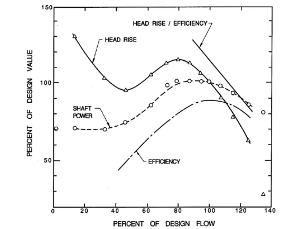
Don’t assume a lower delivered flow always means less power demand. Read the actual power characteristic over the range being considered. Nor should you assume every mixed-flow head curve has the same smooth shape.
In a published mixed-flow pump study by Miyabe and colleagues, the original design showed diffuser rotating stall and a head drop at about 65% of BEP flow. That finding concerns the design studied. It is not a minimum-flow rule for another pump.
The practical mixed flow pump curve question is which regions the proposed model permits, and why. Request clarification where the characteristic or supplied operating range is unclear. Use the actual equipment instructions for starting, valve positions, and controls.
Keep NPSH and submergence separate
Net positive suction head, or NPSH, describes inlet head above the liquid’s vapour pressure. Compare the site value with the model’s requirement and the required margin.
The HI pump-principles reference explains that NPSH3 corresponds to a 3% head drop under the stated test conditions; it is not a guarantee of no cavitation.
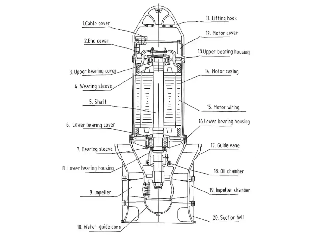
A mixed flow pump curve does not replace an intake review. Check minimum submergence and incoming-flow conditions separately. For a submersible model, water above the unit alone does not confirm that every inlet requirement is met.
Interpret Speed Changes and Parallel Curves Carefully
Use affinity estimates as estimates
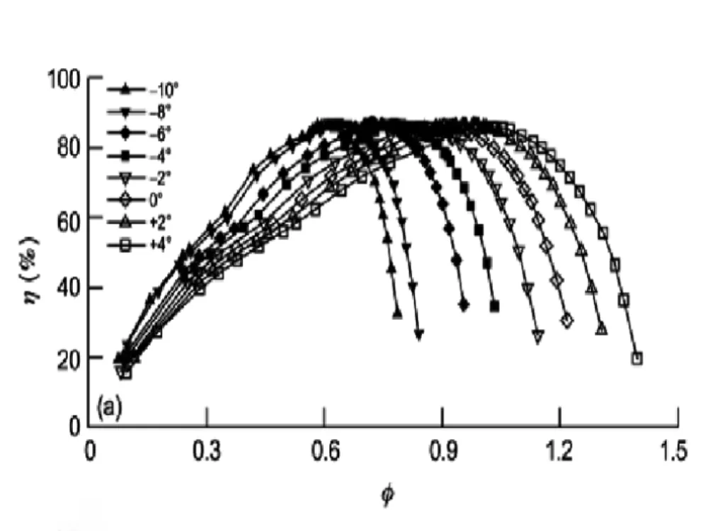
For a fixed impeller and the relevant similarity assumptions, affinity relationships relate flow to speed, head to speed squared, and power to speed cubed. They estimate corresponding points. They do not prove the station’s energy saving or the resulting system flow.
When reviewing a mixed flow pump curve at another speed, request confirmation of the permitted configuration and range. The changed pump characteristic still has to meet the current system condition. Static head can remain part of that requirement even as speed falls.
Do not treat impeller trimming as interchangeable with a speed change. Ask for a curve for the actual proposed impeller. This guide does not establish a universal minimum speed or an acceptable trim for a mixed-flow model.
Add flows at a common head, then review the system
For parallel pumps, construct the combined characteristic by adding individual flows at a common head. Then assess its interaction with the shared system. Two pumps operating together do not automatically deliver twice the flow that one pump delivers alone.
Illustrative scenario: Near the end of a station proposal review, a buyer considers two identical units feeding a common main. The buyer asks for a mixed flow pump curve comparison showing one-unit and two-unit operation against that main’s system conditions. The proposal remains open until the resulting points and limits are addressed.
Keep the running-unit arrangement on each reviewed sheet. If a standby requirement applies, state the capacity that must remain available with one unit out. Don’t leave the reviewer to infer the project’s availability target.
Build a Model-Specific Curve Review Sheet
Record the evidence behind the proposal
A mixed flow pump curve is easier to review when each value has a document reference. Use a simple sheet to separate requirements, supplier proposals, and confirmed information. A blank cell is an open item, not an assumed pass.
| Review field | Entry to request or record |
|---|---|
| Equipment identity | Model, curve number, revision, impeller, stages, speed |
| Site duty | Flow, head, water levels, and system reference |
| Resulting point | Operating flow and head for each assessed condition |
| Efficiency and power | Values, definitions, units, and rating boundary |
| Operating region | Applicable limits and permitted operating pattern |
| Inlet conditions | NPSH basis, margin, and separate intake requirements |
| Open questions | Missing evidence, responsible party, and next action |
Keep the relevant drawing and duty-sheet revisions together. If the pipe route, water levels, or model changes, ask whether the earlier curve review still applies. Send the same revised inputs to each supplier being compared.
Ask for missing documents
Request the model-specific performance curve, power and motor information, dimensional drawing, and applicable operating limits. Ask which test conditions support the data. Where acceptance testing is required, agree its scope rather than assuming a catalogue plot is the agreed test record.
Use Kairun’s QH model information to begin an enquiry. Then request the current mixed flow pump curve tied to the proposed equipment. A general product range cannot replace that document.
Check that the quoted arrangement also fits the intake, outlet, supports, and removal route. These site interfaces are separate from reading the graph, but they still affect whether a technically promising proposal is suitable for the project.
Questions Before Accepting a Curve
Can I combine maximum flow and maximum head?
No. They may occur at different points. Read the required flow and head together on the mixed flow pump curve for the stated configuration, then assess the system interaction and limits.
Is BEP the safe operating range?
No. BEP identifies peak efficiency. Ask for the model’s preferred and allowable regions, including conditions attached to continuous or intermittent operation. Do not draw your own limits from the graph’s outer edges.
Does lower speed prove an energy saving?
No. A speed estimate is not a site energy record. Actual electrical use also depends on the resulting duty, efficiency boundary, controls, and operating hours. Keep those inputs explicit before comparing energy use.
Will two pumps give twice the flow?
Not automatically. Combine their characteristics at a common head and find the interaction with the system. Check each running unit’s duty and loading under the proposed arrangement.
Does the same review apply to axial-flow alternatives?
The document-checking method is useful, but the candidate models and their limits still decide suitability. Use the axial-flow and mixed-flow comparison for equipment background, then examine the actual proposal.
What should I send for a useful review?
Send the duty schedule, water levels, pipeline and intake drawings, liquid data, power supply, and the curve you have. Include the model or quotation reference and mark any assumptions. Ask the supplier to return a written response against those same conditions.
Use the mixed flow pump curve to connect your requirements with the proposed equipment and its documented limits. Request a mixed flow pump curve review from Kairun to request model-specific information and identify the questions that still need resolution.