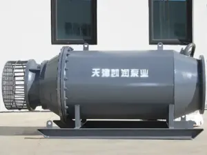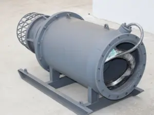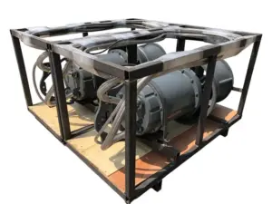
A submersible pump VFD can control speed when the pump, motor, drive, cable, and site conditions support the proposed operating range. Check the lowest intended speed against both the hydraulic duty and the motor’s cooling needs. At a drainage station, a drive may be able to turn the motor slowly while the pump has too little head to deliver useful flow. This guide shows how to spot that gap and build a review sheet for a new or existing mixed flow pump station.
Key Takeaways
- Define the control goal before you size a submersible pump VFD.
- Use pump and system curves to find a useful speed range at each water level.
- Ask the motor and drive suppliers to confirm the cable and output filter together.
- Compare measured input energy over the same delivered duty.
- Record each approved case, the evidence behind it, and the person who reviewed it.
When a Submersible Pump VFD Makes Sense
Start with the service the station must provide
A submersible pump VFD changes the frequency supplied to a compatible motor so the station can vary pump speed. Write down why the station needs that control. A wet well may need to hold a level band as inflow varies. A transfer station may need a target flow under more than one downstream water level.
List the duties that the station must meet throughout a normal day and during events such as storm inflow. Include the flow and head, the range of water levels, and how many pumps run in each case. These facts give suppliers a basis for deciding which pump and drive combination to review. See the submersible mixed flow pump selection guide.
Check the equipment you already have
For a submersible pump VFD retrofit, start with the motor nameplate and the pump model. Find the manual and curve for the actual unit, including any change to the impeller or cable since it was installed. Ask the motor supplier to confirm that the motor supports the drive output and proposed speed range. Record who will confirm the pump limits as well.
For an initial submersible pump VFD review, send the model, nameplate, curve, water levels, and control goal to Kairun. Include the cases that your current station struggles to handle. Contact Kairun.
Find the Usable Speed Range
Find the operating point at each water level
A submersible pump VFD changes the pump curve as speed changes. Plot the pump curve and the system curve on the same axes, with flow on the horizontal axis and head on the vertical axis. Their intersection gives the expected operating point for the assumptions used in the plot. Check it against the required duty and the range the supplier permits.
Build a system curve for each relevant combination of upstream and downstream levels. Static head sets the head difference the pump must overcome before it can deliver flow in a simple open transfer system. Flow adds losses through the discharge path.
Ask for curves at enough speeds to show where the required duty can be met. Mixed flow pump curve guide.
Illustrative scenario, A station proposes running slowly as inflow falls. The receiving level stays high while the wet well drops, so the static head rises. On the plot, the proposed low speed curve fails to reach the required duty. The team flags that case and asks for a revised control plan and a curve at the next proposed speed.
Treat affinity estimates as a screen
For a fixed impeller at corresponding points under similar conditions, flow scales with speed, head with speed squared, and power with speed cubed. At 80% speed, the estimated head is 64% and shaft power is 51.2% of their values at the corresponding original point. Use these estimates to screen a submersible pump VFD proposal and check the result against the supplied curves. Hydraulic Institute Pump Curves.
Look up the curve for your own pump model and speed when you prepare the plot. This Grundfos clip shows a curve lookup in its product tool. Use the same principle when you request documents for a different pump.
Add the limits that a curve alone cannot show
For each duty, check the pump’s permitted range, inlet conditions, and minimum water level. Add any cooling and immersion conditions from the motor and installation documents. A submersible pump VFD speed floor needs to satisfy all applicable checks for the running case.
A pump curve can help establish flow and head, while the motor supplier provides the cooling basis. Pump intake design guide.
Match the Motor, Cable, and Output Filter
Confirm the drive and motor pairing
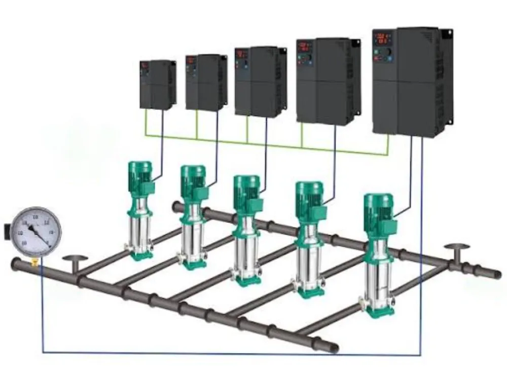
Give the drive supplier the motor type, rated voltage, frequency, and current. Ask it to show which drive rating and installation conditions it used in the selection. Include the proposed minimum and maximum speeds and the expected duty at each end. The submersible pump VFD review should identify the specific motor, drive, and applicable documents.
The Grundfos MS/MMS guide lists a 30–60 Hz range for the motors covered by that guidance. It gives cooling water velocity examples of 0.25 ft/s for 4 inch motors and 0.50 ft/s for 6 to 12 inch motors. Use the applicable motor manual to set your own limits.
Xylem’s Goulds IM180 R04 gives a separate example. At rated temperature and minimum speed, its VFD section calls for 0.5 ft/s water velocity past the motor and specifies a four second ramp down from minimum frequency to power shutoff. The instructions apply to the motors covered by that section.
Include the full cable run
Give the supplier the cable type and the length from the submersible pump VFD output to the motor terminals. Include the wet cable, any extension, and any junction points shown in the layout. The motor and drive documents should state the permitted terminal waveform and the cable or filter arrangement used to meet it. For a retrofit, check whether a route change since installation has made the original cable record stale.
An input side device acts on the supply side of the drive. An output filter acts on the motor side. Ask the supplier to specify the output device, where it belongs, and which drive and motor conditions its selection covers. Check the proposed arrangement against the same cable length used in the submersible pump VFD quote.
Illustrative scenario, A replacement drive quote lists the motor power but the old motor plate is hard to read. The cable route also changed during a panel move. The buyer asks for the original motor record and a verified cable schedule before accepting the quote. The open item stays with the supplier until both inputs are known.
Define Control and Protection Before Commissioning
Tie the signal to a real operating case
State what the submersible pump VFD should control and where the station measures it. For a level scheme, identify the sensor, its location, and the operating band. Show when another pump can enter or leave service. Check the range again for each allowed pump combination.
Write down how the station will respond to a lost or unreliable signal. The control team should document the approved response, the alarm, and the conditions for return to service. Include the station’s power recovery sequence in that review. Ask who accepts each part of the logic and which document records their decision.
Agree what the site test must prove
A submersible pump VFD commissioning record should tie speed and current to the measured duty and water levels. Record the running units and compare the readings with the approved case. Include relevant thermal and seal monitoring and confirm which team owns each check.
Use the pump, drive, and panel documents for permitted settings and site procedures. Submersible mixed flow pump installation guide.
When a reading differs from the expected value, note the date, instrument, and operating case. A flow reading taken before a second pump started may describe a different case from the current reading taken afterward. Log the time of the change so the reviewer can line up both records. Attach the relevant trend rather than copying an isolated peak value into the test report.
Compare Energy at the Same Delivered Duty
Use an agreed meter boundary
To assess a submersible pump VFD proposal, start with the service delivered. Record the pumped volume, head or water levels, running hours, and input energy for the same period. Agree whether the meter covers the drive alone or includes other station loads. Use that boundary on both sides of the comparison.
A shaft power estimate at a matching curve point can help you plan the comparison. The energy bill depends on electrical input and time in service. Compare cases with similar delivered volume and head, and explain any differences in inflow or pump staging. If the station faces wet and dry seasons, record how much each duty contributes to the expected annual use.
Separate a prediction from an observed result
Label the expected value in a submersible pump VFD business case as a forecast. State the assumed hours, water levels, and pump combinations beside it. During acceptance, use the approved measurement plan to record the observed values and document which operating cases the team could test.
If you report energy per unit volume, include the head or level range for that period. The same station can use different energy per cubic meter when it lifts water through a different height. Keep the underlying volume and meter readings so a later review can reproduce the comparison.
Build a Submersible Pump VFD Review Sheet
Make each decision traceable
Use one row per operating case. Put the pump curve revision next to the flow, head, and speed. Add the running units, water levels, cooling evidence, and the motor and drive document references. Use a separate field for any question that a supplier or project engineer still needs to resolve.
| Case | Record together | Evidence to close the row |
|---|---|---|
| Normal transfer | Flow, head, speed, water levels | Applicable pump curve and expected readings |
| Low wet well | Minimum level, duty, speed | Intake, pump range, and cooling evidence |
| High receiving level | Static head and available speed | System curve and required duty |
| Parallel operation | Unit count, staging logic, speed | Approved case and planned site observations |
| Electrical package | Motor, drive, cable, output filter | Written confirmation for the complete pairing |
For a submersible pump VFD package, this simple block sequence can help teams agree where their supply ends. It shows the equipment order for discussion. Use the approved electrical drawings for connections.
Drive output → specified output filter where required → full motor cable route → motor terminals
Illustrative scenario, The controls team plans to add a second pump when the level rises. The hydraulic review identifies the new duty case and checks whether both pumps stay within their permitted ranges. The commissioning sheet calls for water level, flow, current, and speed around that transition. The reviewer can then compare the observed case with the plan.
Keep open items visible
Assign an owner and a due date to each unresolved submersible pump VFD question. If the pump supplier still owes a reduced speed curve, leave the affected case open. If the filter supplier used a preliminary cable schedule, request a response against the final schedule. Save the accepted documents and the test record together so later changes can be traced.
If the site test cannot reproduce a seasonal duty, record what was checked and what remains open. For example, an observed low level case can support that row while a high receiving level case still relies on the submitted curves. Give the untested case its own status and agree how the team will review it.
Questions Before Approving Variable Speed Operation
Can any submerged pump use a drive?
A submersible pump VFD requires a compatible motor and a documented pump operating range. Start with the exact motor type and manufacturer approval, especially for an older unit or one with a single phase motor. Ask for a supported pairing and compare it with the site duty.
What is the minimum frequency?
Use the approved limit for the equipment and operating case. A submersible pump VFD minimum can depend on the flow the pump can deliver, the water level, and the cooling the motor needs. Record the controlling condition so an operator can see why the limit applies.
How long can the motor cable be?
Ask the drive and motor suppliers to review the complete cable route and the output device. Give them the cable type, length, motor rating, and drive model. Use the written confirmation for that pairing when you specify the panel and cable.
Will it cut the power bill?
Compare input energy for the same delivered service. A submersible pump VFD can give the station another way to meet varying demand. The measured result depends on the duties, levels, equipment, and running hours.
What should I send for a review?
Send a case sheet with flow, head, water levels, the running pump combinations, and the proposed control goal. Include the curves, motor nameplate, drive model if selected, and cable schedule. Mark any limits that still need supplier confirmation.
For your next submersible pump VFD enquiry, send that package to Kairun so the equipment discussion can start with the actual duties and site conditions. Contact Kairun.