Vertical axial flow pump installation starts with approved drawings, intake water levels, and foundation checks. Confirm the drive setup, fit and measure the pump, then complete the required oil or water supply checks, protection tests, and wet commissioning.
A pump can fit its opening and still fail its first wet test. The civil crew may have built to one drawing while the pump arrives to another. A discharge pipe can meet its flange yet pull the shaft out of alignment when tightened.
If you’re coordinating lifting, mechanical work, and electrical completion, these shared tasks need a clear checklist. This guide turns vertical axial flow pump installation into recorded hold points. It explains what to inspect, where to find each limit, and which issues must be closed before starting.
You’ll work through submergence, pipe support, shaft checks, startup readiness, and the commissioning log. The guide draws on maker manuals and Hydraulic Institute guidance, with each source kept within its scope. Use it to plan the work with qualified site staff; the supplied pump’s current manual and approved drawings set the actual dimensions and limits.
Key Takeaways
- A long-shaft pump with a motor above water needs different checks from a pump with a built-in submerged motor.
- Minimum submergence must address intake vortices and the pump’s suction needs; one fixed depth won’t suit every station.
- Record shaft alignment before and after pipe connection, using the required test method and limits.
- A blanket closed-discharge startup rule is unsuitable for vertical axial flow pump installation; obtain the model-specific valve sequence.
- Accept commissioning against agreed readings and protection tests, then keep the baseline for later checks.
Plan Vertical Axial Flow Pump Installation
Identify what is being supplied
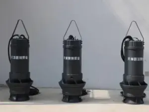
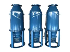
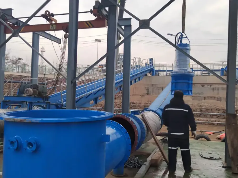
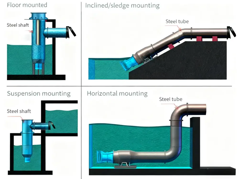
The word “vertical” tells you how the pump stands. Check the sectional drawing to see how it is driven. The motor may sit above the liquid and drive a long shaft, or form a submerged unit with the pump.
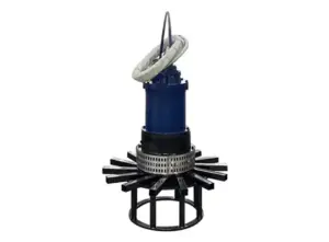
For a long-shaft unit, vertical axial flow pump installation includes column joints, shaft bearings, driver alignment, and the required axial setting. A pump with a built-in submerged motor needs checks of its seat, anti-rotation features, lifting system, and cable support. A vertical discharge tube alone doesn’t tell you which type you have.
Next step: Use Kairun Pump’s vertical pump catalog listing as a starting point. Ask for the sectional drawing and current manual for the exact proposed unit before fixing site details.
Agree on the document set
Keep the approved foundation and intake drawings, parts list, motor data, bearing-supply guide, and control schedule together. Add the pump curves and agreed commissioning limits. Record revisions so the team knows which files govern vertical axial flow pump installation.
Fictional scenario: Jordan plans a drainage-station lift for Monday morning, but the civil crew holds drawing revision B while the supplier’s unit uses revision C. They compare the discharge direction and anchor positions before the lift. The mismatch sends the drawings back for review, keeping the pump out of an opening that needs to be checked. The revised lift plan then uses one agreed drawing set.
Name the people who release each stage. The mechanical lead records alignment, the electrical lead verifies protection, and the commissioning lead accepts the startup plan. This gives each part of vertical axial flow pump installation an owner and a signed record.
Verify Foundation, Submergence, and Intake Flow
Survey the intake from a common datum
Before vertical axial flow pump installation proceeds, measure the base height, pump setting, and water levels from the same reference. Mark the minimum allowed operating level and the datum used for submergence. Don’t measure from a random point on the motor or casing.
Submergence is an intake-design requirement, not just the amount of pump body under water. The Hydraulic Institute’s submergence guidance explains that depth helps prevent strong air-core vortices. It also states that more submergence may be needed to meet the pump’s required Net Positive Suction Head (NPSHR).
Check both needs. Water over the pump does not prove that suction conditions are adequate. Nor does a suction-head check prove that flow enters the pump evenly.
The approved intake design must cover the lowest running level, inlet shape, nearby walls, floor clearance, and other pumps running together. Inspect the actual channel for debris, uneven inflow, and blocked paths. Check the screens and how their condition affects the flow.
For more background, see the cavitation causes and site checks. That guide covers suction risks; its specific submersible limits are not settings for a long-shaft pump. Keep the actual intake design with the site survey.
Record submergence at the planned commissioning level as well as the design minimum. During the test, watch for a drop in level that changes submergence while other pumps start. One static water-level reading cannot describe every running state.
Release the foundation and lifting route
Foundation checks for vertical axial flow pump installation cover support loads, anchor positions, mounting faces, grout, and access for removal. Check cure and bolt-tightening rules against the project files. A grout waiting time from another job is not proof that this base is ready.
The Sintech vertical mixed-flow and axial-flow manual, pages 25–40, covers these check areas. It includes pipe supports, shaft fitting, alignment, and bearing lubrication. These are useful inspection topics, but its numerical settings apply to the units it describes.
For vertical axial flow pump installation, confirm the lift weight, approved lifting points, headroom, and temporary supports. Do this before moving the pump. Use the site’s lifting plan to control the load and keep people clear.
Check the final pump position against the approved intake clearances. Keep the submergence reference visible in the survey record. Confirm that future removal can follow the planned route without damage to cables or nearby equipment.
Assemble the Column and Check Shaft Alignment
Inspect and assemble in the specified order
Long-shaft vertical axial flow pump installation needs clean mating faces, sound threads, the right shaft sections, and the specified bearings and couplings. Check for transport damage before parts disappear inside the column. Measure the shaft at the points and to the limits given in the manual.
Follow the supplied steps for each shaft and column joint. Use the required temporary supports and make each check before adding the next part. If a section binds, stop and find the cause.
Check thread engagement, shaft position, and free movement where the guide requires them. Don’t use the next joint to pull a damaged part into place. A pump that can be bolted together has not necessarily passed its fit checks.
Keep alignment readings with the gauge setup and reference points. A note saying “alignment checked” gives the next team too little to repeat the test. Vertical axial flow pump installation records should show the readings, limits, date, and person responsible.
Set the rotor and connect the piping
Impeller position, shaft end movement, coupling gap, and thrust-bearing setup depend on the design. The Sintech manual gives different impeller-setting methods for axial-flow and mixed-flow versions. Use the supplied pump and motor guides, not a lift distance or turn count from a different unit.
After the first alignment check, bring the supported discharge pipe to the flange without forcing it into place. Recheck alignment after connection and the required final tightening. If readings change, inspect the pipe supports, flange fit, base, and pump assembly.
Fictional scenario: Morgan records shaft alignment with the discharge spool disconnected, then repeats the checks after its flange bolts are tightened. The new readings fall outside the project’s agreed band, even though the pump turned freely before connection. They isolate the pump and ask the responsible team to check the spool and support fit. After correction, the readings meet the agreed limit, and the record keeps both sets.
For a submersible unit, vertical axial flow pump installation follows a different path at this stage. Check the required seat, seal, anti-rotation fit, and cable route. Don’t add long-shaft alignment steps to a unit with a built-in motor just because both pumps stand vertically.
The result is a measured baseline for the fitted pump. Save it before covers, guards, and pipes restrict access. It will help the team judge later changes and accept commissioning results.
Vertical Axial Flow Pump Installation: Prestart Checks
Establish lubrication and electrical readiness
Find out whether the shaft bearings use product water, an external clean-water supply, or oil. Confirm any pre-lubrication, venting, flow check, or loss-of-supply trip required for that setup. A unit with a built-in submerged motor may have a different system.
This matters during vertical axial flow pump installation because similar pump names can hide different bearing systems. Don’t use one oil quantity, drip rate, or pre-wetting time across all units. Record the required method and check that the supply is present.
Qualified electrical staff should check the supply, earthing, cable condition, insulation, and protection against the motor and control files. Confirm rotation using the maker’s method and stated viewing direction. The name “axial flow” does not tell you whether the shaft turns clockwise.
Do not dry-jog the fitted pump without an applicable test procedure. Where the guide calls for a separate motor test, follow its exact steps and safeguards. Treat the motor, pump, and thrust-bearing details as one coordinated setup.
If the supplied unit is submersible and uses a variable-frequency drive, the submersible pump VFD guide lists control questions to discuss. It does not approve a long-shaft motor’s speed range. Set commissioning limits from the selected pump, motor, and station design.
Sign the hold points
Use this vertical axial flow pump installation record template to agree on the evidence needed for each release. Enter actual readings and file references. A tick without a test result leaves the next team guessing.
Low-level protection must preserve the required submergence. Include any needed allowance for a falling level and the time it takes to stop. Check the control logic before handing the system to the operator.
| Hold point | Evidence to record | Release by project role |
|---|---|---|
| Documents and structure | Pump identity, drawing and manual revisions | Project engineer |
| Foundation and intake | Survey, supports, clearances, submergence reference | Civil/mechanical leads |
| Mechanical assembly | Alignment readings, rotor setting, bolt records | Mechanical lead |
| Electrical and controls | Rotation method, protection settings, interlock tests | Electrical lead |
| Wet commissioning | Startup plan, instruments, test conditions | Commissioning lead |
| Handover | Accepted baseline, as-built records, open actions | Owner’s representative |
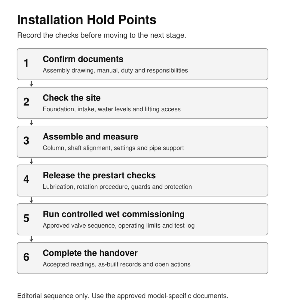
Installation hold points, shown as an editorial sequence. This is not a manufacturer’s assembly drawing or a source of engineering dimensions.
Finish guards, access controls, and site communications before the start release. In vertical axial flow pump installation, a missing protection test stays open even when the mechanical work looks complete. Resolve safety and operating-limit issues before signing permission to start.
Record the First Wet Commissioning Run
Confirm the discharge path before starting
The commissioning plan must state the discharge path, valve positions, venting, starting method, and allowed operating range. Don’t borrow a closed-discharge startup rule from a different pump design. Vertical axial flow pump installation needs a start plan matched to the supplied pump and connected system.
For a specific example, the Flygt P7030/P7035/P7040 manual, PDF page 61, prohibits running against a blocked discharge line or closed discharge valve. This maker’s document is hosted by a third party. Its rule applies to those submersible models, not to every long-shaft pump’s valve opening or timing.
If the supplied instructions conflict, obtain a clear answer for that model before wet commissioning. Don’t choose a valve setting because it feels familiar. Keep the agreed steps and their source in the vertical axial flow pump installation file.
Record conditions, readings, and stop decisions
Check the starting water level and submergence, clear the discharge route, and confirm that instruments and communications work. Start only after the required site releases. Observe the pump through the test states set out in the commissioning plan.
Record the following where they apply, with units, test points, times, and instrument details:
- Flow rate, total dynamic head, speed, and motor current
- Intake water level and any change during the run
- Vibration at the agreed test points
- Bearing temperature and oil or water supply condition
- Alarm, trip, and restart-test results required by the plan
Compare readings with the agreed limits. A temperature or vibration value from another manual is not an acceptance limit for your pump. Keep the measurement method with the result so later tests can use the same basis.
During commissioning, stop through the approved steps if a trip occurs or readings exceed the stated limits. Find the cause of rubbing, loss of bearing supply, air entry, or unstable flow before restarting. Keep repeated starts within the motor’s allowed starting duty.
After the run, add test conditions to the alignment baseline and submergence record. For vertical axial flow pump installation, these combined records help the team trace a fault to the pump, intake, or controls. Close the commissioning action log before accepting routine service.
Next step: If drawings, intake levels, or startup instructions disagree, discuss the installation documents with Kairun Pump before the wet run. Include the supplied model, drawing revisions, duty point, and the question to resolve.
Installation Questions From Site Teams
Can I use a vertical turbine pump installation procedure?
Only where the supplied design and maker’s guide allow it. A turbine manual may explain a related shaft system, but the name does not prove an axial-flow impeller. For vertical axial flow pump installation, first confirm the pump type, driver, thrust setup, bearing supply, and build sequence.
How much submergence does the pump need?
Use the approved intake design and the exact model’s minimum running level. Required submergence depends on the inlet, flow, approach path, and suction needs. Vertical axial flow pump installation should record the datum and the controlling requirement, rather than adopting one depth in metres for every site.
Should I close the discharge valve before startup?
Do not use a blanket closed-valve rule. Get the actual model’s startup guide and system valve sequence, and resolve any conflict before commissioning. The cited Flygt example prohibits closed-discharge running for its listed models; other units need their own confirmed steps.
Which documents should be ready before installation?
Have the current pump, base, intake, bearing-supply, motor, and control files, plus curves and agreed test limits. The vertical axial flow pump installation checklist should name the revision of each. Include alignment checks, minimum submergence, protection tests, and the commissioning log so the team knows what to prove before starting.
Complete the Installation Handover
Complete vertical axial flow pump installation by handing over proof of the accepted condition. The owner needs the actual pump details, alignment baseline, intake level reference, and settings for the supplied machine. Signed records give the operating team a clear starting point and help them repeat later checks.
Check that the file holds approved drawings, measured site checks, protection-test results, and the wet commissioning log. State the water levels and submergence used during the test. Include the running conditions and instruments so a later reading can be compared on the same basis.
List each open action, its owner, and whether it blocks use of the pump. Keep the maintenance guide and running limits with the commissioning baseline. These details let the next team see what passed, what still needs work, and which settings they must preserve.
Next step: Send Kairun Pump your project details, including flow, head, media, water levels, and the proposed setup. Request the model-specific files needed to plan your vertical axial flow pump installation.